Editor’s Note: For this article, ƒ/D is pleased to present a contribution from guest author Delio Ansovini. We’ve featured Delio’s work previously on ƒ/D, where he showed an expert hand at still life subjects. If you look at his work enough, one thing that quickly begins to stand out is his exacting attention to detail in the framing of his shots. As a trained engineer, he has a firm grasp on the geometry involved in a camera’s configuration, and he’s graciously offered to put together some thoughts on how he approaches the subject for us. So without further ado, we present Delio Ansovini’s take on Pinhole Camera Geometry.
Geometry matters – because it is the geometry of a pinhole camera that defines the image taken with it.
The pinhole diameter, the size of the negative, the distance and position of the film and pinhole from each other, and the orientation of the camera toward the subject all affect the resulting image for one simple reason: light travels in a straight line.
Perspective geometry, which is stated simply as ‘…a way to give an illusion of three-dimensional depth when drawing on a flat surface’, very reliably does the rest.
Once we understand these concepts and techniques, the lack of a viewfinder doesn’t need to stop us from pre-visualizing the results.
First: What are view lines?
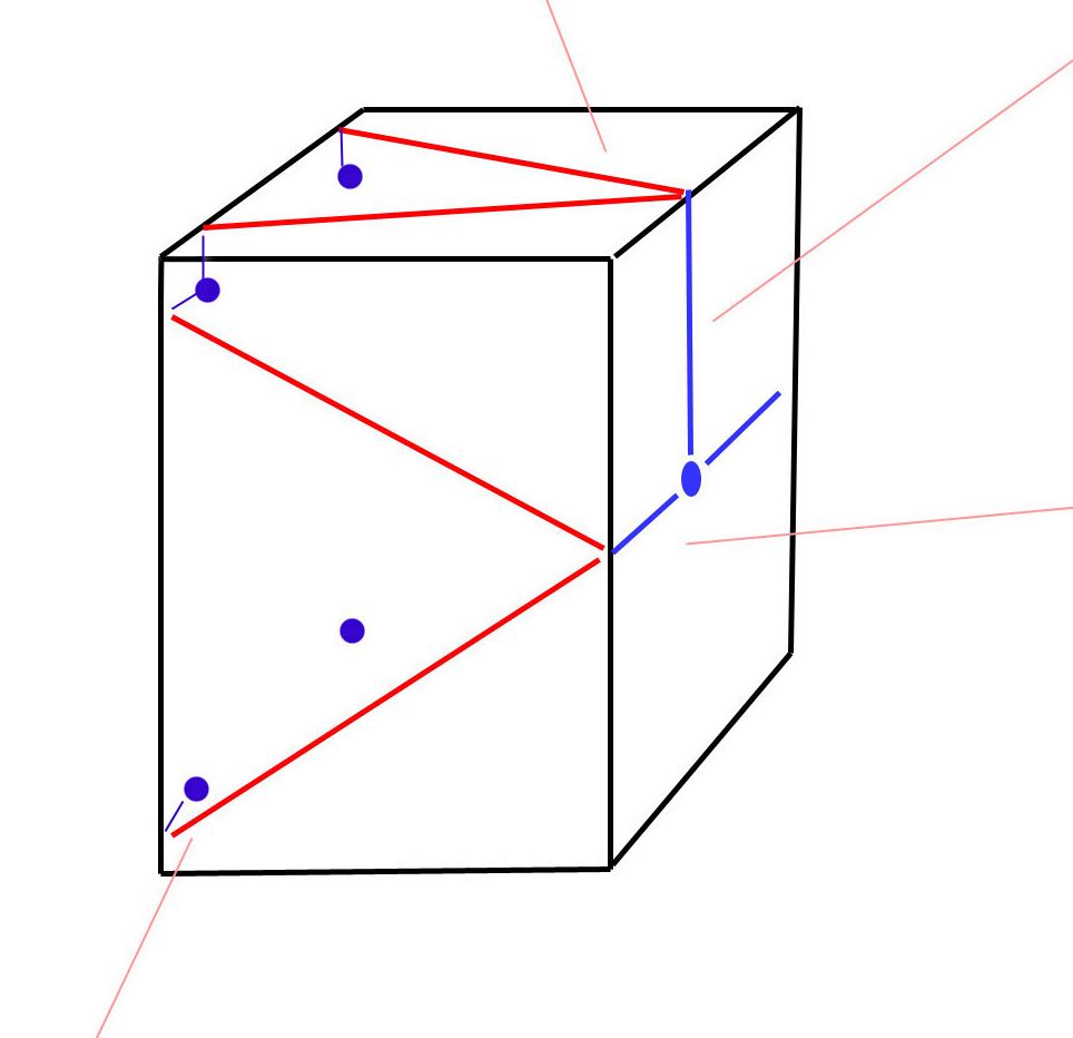
View lines provide us with a visual axis that defines what will be captured by the pinhole in the final image. The lines are a simple tool that you can apply to any camera to help with your visualization.
[singlepic id=78 w=350 float=left][/singlepic]Top Red View Lines
By visually following the line from the camera, you can observe what is included in the shot. Anything inside the extended two lines will be in; anything outside them will be out of the shot. It helps to use a pointer – I use a pencil positioned on the view line and I look at the sharp end pointed toward the subject. Others use 3 screws and line up the 2 screws with the subject. Regardless of your method, the top red lines are to help you visualize what will be included from left to right in your shot.
Side Red View Lines
Just as explained with the top lines, the red lines on the side of the camera extend from the edges of the film plane to the axis with the pinhole. For a 4×5 negative, the corners of the frame holder opening are the points to project to the sides of the box. For 6×6 the corners of the film mask are the ones to use. Again, like the top red view lines, you can visually follow the lines from the camera to the subject to visualize what will be in the shot, but for these lines, you’re visualizing what will be included from the bottom to the top of the shot.
Blue Horizontal and Vertical Lines
The blue projection lines from the pinhole to the edges of the camera are important to consider when applying your view lines. If the pinhole is recessed from the front plane of the camera, recess the convergence point of the view lines by the same amount.
[singlepic id=80 w=150 float=right][/singlepic]The Four Converging Planes
If you extend out the Red View Lines diagrammed above, you have an ever broadening plane extending from the front of the camera. The result is that the four intersecting lines generate four converging planes that extend from the film plane and intersect at the pinhole, then extend into the space beyond the camera.
To the right is my 4×5, f175 with the 130 deg view lines made with 2mm wide automotive vinyl pin striping. Note how if we visualize the extension of the View Lines towards the subject, we can see what the camera sees at that distance.
Second: Something borrowed from lens photography: the diagonal angle of view
You can find this angle value the fun way (do-it-yourself for those who like trigonometry) or “cheat” and use the app given below. Two factors directly change what the pinhole camera registers on a flat negative. First is the distance from the pinhole to the negative, and second is the size of the negative.
First, let’s look at the size of negative. Imagine that the image projected from the pinhole is a cone with a circular base sitting on top of a 6×6 negative while you are looking at the pointed apex. For a square negative, the vertical and horizontal perspective would not change since[singlepic id=77 w=350 float=left][/singlepic]the cone base will be tangential to both the vertical and horizontal sides, or for that matter with a larger diameter to each opposite corner of the negative.
The geometry will be totally different if the negative is, say 6×12, and we keep the height of the cone (the camera focal length) constant. If we look at the angle formed by the diagonal of the negative (from corner to corner), it is much larger than the 6×6 negative, even though the cone angle remains constant for both the vertical and horizontal planes as before. We call this diagonal measurement from corner to corner of the negative the diagonal angle of view. The diagram helps to visualize the concept.
This means that if we want to obtain a certain geometric perspective in our pinhole image and, for whatever reason, we have to change the negative size, we can use the diagonal angle of view as the constant factor while changing the distance from the pinhole to the negative. In short: a 6×6 cm. pinhole camera with focal length of 28mm has a diagonal angle of view of 113 deg.; the same as an 8x10in. (20.3×25.0cm.) pinhole camera with focal length of 106mm.
The two cameras will give you the same geometric perspective and both would be considered rather popular wide-wide angle pinhole cameras. Instead of the above, you can find the diagonal angle value with this handy program or this handy website. Both the program and the website have features that calculate the diagonal of view based on your camera measurements.
There are also personal reasons why I consider the diagonal angle of view important in designing or choosing a camera for a specific shot: I enjoy being able to have some control over the image. Moreover, I hate cropping 2/3 of the negative needlessly – film is too expensive to waste.
The following photos illustrate the visual difference in geometric perspective according to the diagonal angle of view and camera position on a 6×6 negative.
[singlepic id=81][/singlepic]
[singlepic id=83][/singlepic]
[singlepic id=84][/singlepic]
[singlepic id=85][/singlepic]
Note: the almost normal perspective lines in the first, the predominance of the hand railing on the second, and of course the lines divergence and convergences on the last two.
Third: light gets tired travelling longer paths
The truth of the matter is that the path from the pinhole to the corners of the negative is longer than the one to its center. And it gets darker and mostly “unpleasant” for diagonal view angles above 130 deg.
On the other hand we photographers do love the drama of the vignette, the exaggerated convergence of lines, and the elliptical distortions in the corners. But there are limits, so we crop what we can’t distinguish or appreciate anymore.
I settled on 130 deg in my designs, based on what I like and my processes. Other will choose according to their own objectives and skills.
Some time ago I made a 4×5; f140; 21mm focal length; 149 deg diagonal view angle camera; following are the camera and the drastically cropped image taken with it.
[singlepic id=72 w=325 float=left][/singlepic] [singlepic id=87 w=335 float=left][/singlepic]
At this point it is not only about geometry anymore: film used, exposure methods, developing products and methods all will contribute to getting details on the corners of your image and make the vignette less severe.
But above all it will be what you like and what you see in the images that you have made that counts. This is what makes pinhole photography so amazing.