Over a year ago we presented a fantastic guest article by Delio Ansovini covering the important aspects of camera geometry in pre-visualization of your pinhole photos. Today we are rejoined by Delio as he walks us through his IR process.
IR, or Infrared, is one of the more dramatic techniques available in film. Rather than exposing on the visible light spectrum that we see, Infrared film is exposed by the invisible Infrared waves that have just a bit longer wavelength than we can see. More importantly, to our purposes, the aesthetic of IR is dramatic because of the way that certain materials reflect more IR than others.
Shooting IR with a normal camera is a challenge, doubly so with a pinhole camera. The wavelength properties of pinhole, the film handling of IR, and reciprocity failure all combine to make a unique problem set. Below, Delio has put together his notes on learning IR pinhole. We hope this helps you on your journey to IR pinhole greatness!
On B/W Infrared Photography with 4×5 pinhole cameras
By Delio Ansovini
I started experimenting with infrared films using a pinhole camera in 2012 with a lens-less 6×9 Ikonta. It came out as an f316 with the R72 filter taped on to the mechanical shutter, all in front of the pinhole plate. Certainly it was awkward but…a functional arrangement. The Efke 820 was still ready available in the local stores so I made it my choice for infrared work.
There followed a couple of weeks of shooting around the local parks, all in the mid-daysun; high winds pushed the white clouds high in the sky across the frame creating very blurred streaked photographs. The poignant images were published in Blur Magazine in 2012.
Encouraged by how successfully they turned out, I ventured into the 4×5 format thinking that: aside from the much extended exposure time, there was not much difference in infrared photography between using a pinhole or a camera with a lens. What blessed ignorance; but here is the story one step at a time.
The film speed and exposure
It’s difficult to pinpoint an ISO rating for IR film because the ratio of infrared to visible light varies greatly from scene to scene and of course we can’t judge the difference since we can’t see IR reflections (IR frequencies are out of range for our eyes); nor can your off-the-shelf light meter help since it is calibrated for visible light.
Other factors affecting speed are the type of filter, the developer being used, and how you process the film. Some broad assumptions and decisions had to be made to eliminate the multitude of variables. Here’s my quick guide on how I initially approached the issues (since then revised):
- I assumed that the sensitivity to visible light of the Efke IR820 was ISO100,
- I used only the R72 filter and I assumed that factor was 5 stops.
- I set the light-meter (L358) to ISO3, the lowest setting available. That is 5 stops from ISO100 using incident readings
- I limited the pinhole 4×5 cameras to be used to the f175 and f250 only.
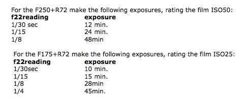
- I used incident light readings at f22 and converted the exposure time from f22 to the pinhole camera f# using the following factors:
- for f175 multiply the f22 exposure time by 63.3
- for f250 multiply the f22 exposure time by 129.1
- Add the reciprocity correction as in the following table.

Development process
With the exposure method as established above, the first few 4×5 exposures were developed in a Unicolor tank using the Kodak Tmax Developer, 1+4 for 7minutes, all at 20C, in a continuous reversing agitation mode. I used 2 baths of water as stop wash for 3 minutes in total; fixed in Kodak Fixer for 10 minutes; washed for 20 min and hung to dry for 2 hours.
The results or lack of them
The negatives were underexposed; furthermore I noticed serious IR seepage through the camera’s felt gasket on both cameras and film holders dark slide when the camera was positioned in full sun for the required exposure.
I also felt that the TMax developer had no compensating properties at all, in fact rather useless for the application!
In short: neither my 4×5 cameras made in wood and Gator foam board, nor the old 4×5 dark slide in the aging film holders were infrared-proof. The relatively aggressive Tmax developer did not help either.
The fixes
The following procedural changes were implemented with good results with the 4×5 Efke IR820 film and the unmodified existing cameras and film holders.
- Wearing latex gloves to handle the IR film for loading in full darkness, my fingerprints somehow became visible on the developed negatives if I did not use gloves.
- Carry 3 film holders in an aluminum foil covered black plastic envelope. I used a recycled 8×10 film black plastic pouch, lined on the exterior with aluminum foil and double-sided sticky tape.
- Load the film holder onto the camera in the shade and wrap the aluminum shield around the 3 sides of the camera covering the felt edge. Making sure the shutter is closed and locked in place, remove the blind slide and cover the top of the film holder with the shield.
- Position the camera on the tripod in the sun for the shot.
Calculate the exposure as before but rating the film as follows:

• Open the shutter for the timed exposure.
Revised development process
Blown-out highlights are not my favorite attribute in a photograph, so I tried what I know works well with panchromatic films. My notes on the revised process read:
Film used: 4×5 Efke 820IR rated ISO25, f175, Filter R72, Exposure 15 minutes.
Film development: AdoxAPH09 1+100 for 15min In Rotary tank, continuous reversing; water wash 3 min; fixing 10 min.
The results after the fixes
All much better, no blow-out of the highlights, no elaborate PS editing with curves or masking, therefore I was quite happy.
However; the aluminum foil wrapping of the camera sitting on a tripod for 20 minutes or so did generate some amusing conversation with the curious (or alarmed?) passersby.
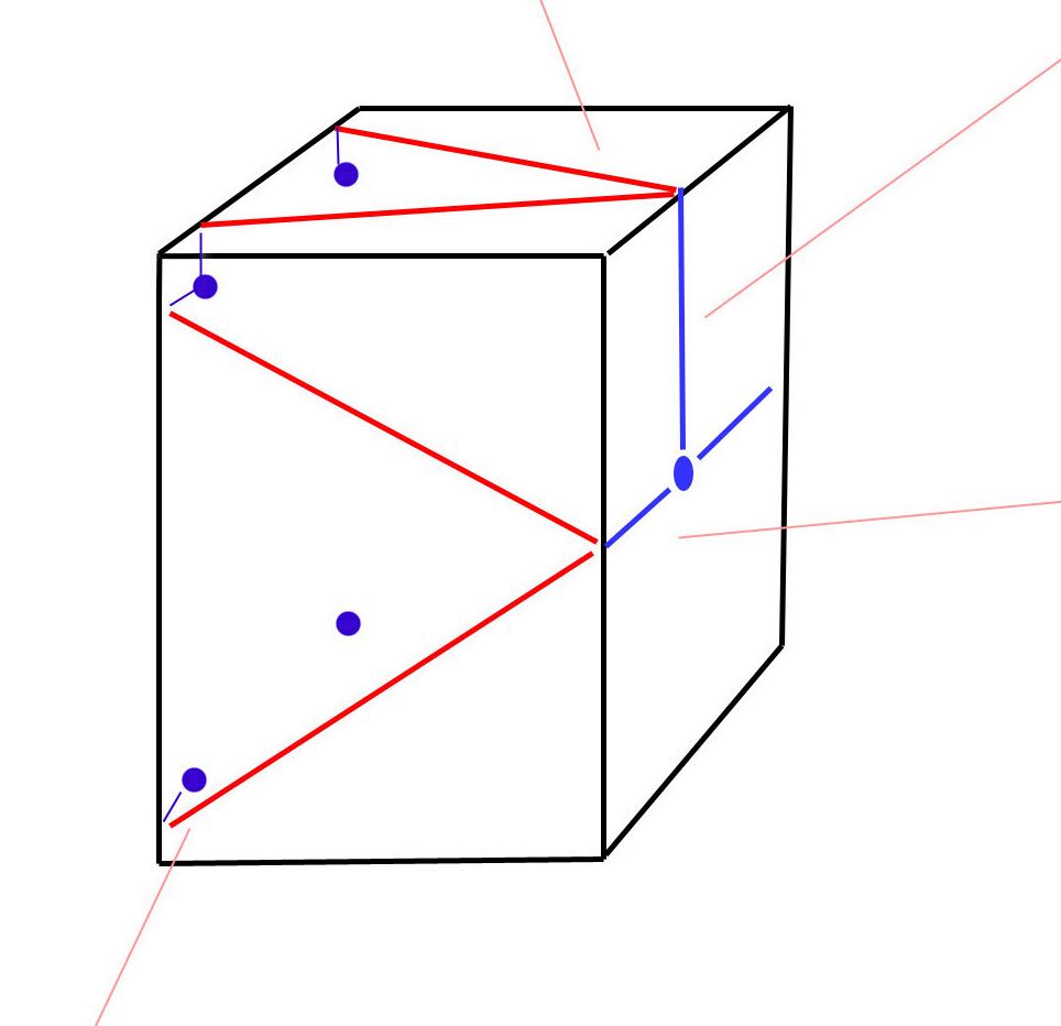
For that I devised a wooden back cover lined with foil, as shown in the photo. It is classier…
[singlepic id=415 w=600] [/singlepic]
Illustration legend:
1. The f250 back with the aluminum lining of the back cover
2. The back cover mounted on the camera
3. The camera front with the shutter (aluminum foil is lining the inside of the cap)
4. The R72 filter mounted in the camera inside. One of the three tabs is rotating so that the filter can be removed and the camera used with normal Pan film
Good things don’t last very long
First they discontinued the 4×5 Efke 820IR film, and then some chemist decided to change the formulation of the Adox APH09 so that what I used to dilute 1:100 I now have to dilute 1:40.
And yet I do sympathize with the individual in the German laboratory. I use only 120cc of APH09 working solution to develop 4-4×5 negatives. At 1:100 dilution it means 24 drops of APH09 concentrate from the 500cc bottle available. However; the compensating characteristics of the APH09 previous version are no longer there.
Fortunately we can be resourceful
Just a few weeks ago, I decided to revive two chemicals that I stored in glass jars- one is Sodium sulfite and the other is Metol. I purchased some distilled water and that’s all I needed to make the old D23 and, try it on a new Maco IR 820c.
New? Not quite, just new on eBay and available at a reasonable price. I did find this link to the film datasheet useful; in fact, I wish I had come across it earlier, although I enjoy the experimentation process.
http://www.maco-photo.de/files/images/MACO_TA820c_ENG.pdf
In reference to the making of the D23
It’s easy, even I can do it; and very economical. As far as I know there is only one formula for making this developer, the one listed in Ansel Adams’s book “The Negative”.

Both chemicals can be purchased in powder form from Photographer’s Formulary, or as prepared solutions from B&H and others.
Well, the results of these two last process changes are shown in the photographs accompanying this article, and the details for each photograph are listed in my usual cryptic fashion. At least now you know what’s behind all the puzzling verbiage.
A warning to all that intend to use the data in this article: it works for me but it may be quite different for you. The major difference is in the agitation of my rotating developing tank which is quite unusual and energetic and cannot be controlled. At least the developing times, contrast and sharpness all reflect that.
In reviewing my writing along with the data published on the MACO IR820c data sheet referenced above, I become aware of a great discrepancy in the reciprocity factor to be used. This subjects maybe something to look into closer.
IR Sample Images
[singlepic id=422 w=600]The Midle of the Swamp, ©Delio Ansovini[/singlepic]
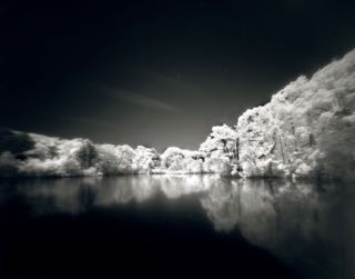
[singlepic id=418 w=600]The Ducks Pond, ©Delio Ansovini[/singlepic]
[singlepic id=417 w=600]Seat in the sun, ©Delio Ansovini[/singlepic]
[singlepic id=419 w=600]The Dunes, ©Delio Ansovini[/singlepic]
[singlepic id=421 w=600]The Rivulet, ©Delio Ansovini[/singlepic]
[singlepic id=420 w=600]The House on Fire, ©Delio Ansovini[/singlepic]
[singlepic id=416 w=600]Casa Loma Stables, ©Delio Ansovini[/singlepic]
Data for the photos presented
The swamp
The Duck Pond
Seat in the sun
The dunes
The rivulet
4×5 Pinhole
f175, L=35mm, Photo location: H. Park, Ontario
Date: June 2016
Film used: MACOPHOT-IR820c
Rated ISO 25 Exposure: 30 minutes
Filter.R72; Lighting: None;
Negative development: D23 1:1 for 11min In a Unicolor Rotary tank, continuous reversing agitation; no water wash; Neg. scanned 1200 dpi, RGB, spotted, duotone; framed to size.
——————————————-
The house on fire
Casa Loma
4×5 Pinhole
F250, L=50mm, Photo location: Casa Loma, Ontario
Date July 2016
Film used: MACOPHOT-IR820c
Rated ISO50, Exposure: 24minutes
Filter.R72; Lighting: None;
Negative development: D23 1:1 for 11min In a Unicolor Rotary tank, continuous reversing agitation; no water wash; Neg. scanned 1200 dpi, RGB, spotted, duotone; framed to size.
![]() As always, we found some great fresh pinhole work. You can see July’s full gallery and links to past months here.
As always, we found some great fresh pinhole work. You can see July’s full gallery and links to past months here. We explored the impressionistic views of life slipping by in Lena Källberg’s Decisive Movement work.
![]() We interviewed Michael D Hawley, the talented professional photographer from the Pacific Northwest, and learned how he grew up in photography and how it shaped his pinhole work.
We interviewed Michael D Hawley, the talented professional photographer from the Pacific Northwest, and learned how he grew up in photography and how it shaped his pinhole work.![]() Howard Moiser brought us a new perspective on movement in his Relative Movement series.
Howard Moiser brought us a new perspective on movement in his Relative Movement series.![]()


