Category Archives: Articles

Smartphone Apps for Pinhole Photographers

Smartphones today – whether Android or Apple – are of course ubiquitous anymore. It’s hard to find a social setting where there’s not a solid portion of the group with their faces stuck in their phones. The change in social interaction can become tiresome and, in some cases, worrisome. But of course, there’s tremendous good that we get form our phones, and today we’re going to cover one such area.

For the modern pinhole photographer, your phone can be a true godsend. For today’s article, we’re going to cover a few areas where your smartphone can make your life in pinhole photography much much easier.

Exposure Meters

Pinhole Assist (iOS only $2.99)

[singlepic id=208 w=225 float=right] [/singlepic]The aptly named Pinhole Assist (available on the app store) is the first phone app light meter I ever tried for pinhole photography. When you first open the app, you’re presented with a display from your camera, along with exposure readings based on the input ISO and ƒ-number. The upfront operation is simple: once you set the ISO (film canister icon) and aperture (aperture icon), you compose your scene in the view and the app gives you the exposure time. Playing with the buttons and menus, you’ll quickly discover some great features to help you get the right exposure. Diving deeper though, there’s special sauce to this app.

After you get your camera ISO and aperture dialed in, hit the “hamburger menu” in the top left (the three lines) – in this menu, you can choose a film if you like, and you’ll see there’s options for dialing in an exact aperture in case yours wasn’t in the regular aperture menu. Now that you have your setup exactly right, hit the “Add Combo” button in the menu, and enter a name. You’ve now saved your camera preset – this feature is a lifesaver if you have multiple pinhole cameras to manage.

Next, when you’re framing your scene in the app’s viewfinder, it’s using a general evaluative metering mode. Want to meter on something specific? Tap an area in the scene, and note the square – that’s a weighted meter now! Not quite a 1º spot, but it’ll do!

Pocket Light Meter (iOS Free, Android $0.99)

[singlepic id=209 h=200 float=left] [/singlepic]The Pocket Light Meter app is available for both iOS (app store) and Android (Google Play) and offers a solid alternative from the Pinhole Assist. This app lacks some features of Pinhole Assist – notably the ability to save camera profiles, set custom aperture values, and auto calculate reciprocity failure. But what it lacks in complexity, it makes up for in zen simplicity: dial in your ISO and aperture, and it starts measuring.

If you only have one pinhole camera, or you’re just testing the waters, Pocket Light Meter is a good option. The square in the middle acts as a center weighted average meter, and you can tap around the viewfinder to adjust this metering target. The larger viewfinder makes it helpful when double checking to make sure you’ve metered the exact area you need.

Reciprocity Management

Reciprocity Timer (iOS only $1.99)

[singlepic id=211 h=200 float=right] [/singlepic]One thing that we pinholers often run into is reciprocity compensation and management – so often that you may as well be sure you’re managing it correctly. Reciprocity Timer is available on the app store for $1.99, and was originally built for large format photographers. Over the years the app has built quite the reputation for having very exacting reciprocity tables – an advantage that can be crucial for color film such as Ektar.

But Reciprocity Timer doesn’t stop there. It has built in compensation for filters and includes a stopwatch function. Pinhole Assist also has a stopwatch built in, but for the shooter that uses films susceptible to reciprocity, it’s a very helpful app to finish your workflow in.

In the Darkroom

Massive Dev Chart (iOS $8.99, Android $8.99)

[singlepic id=210 h=200 float=left] [/singlepic]Many pinholers are processing their own film, and if you’re processing your own film, you need the Massive Dev Chart, available for Android on the Google Play Store and iOS on the App Store. The Massive Dev Chart is a compilation of a HUGE amount of film and development time combinations. In addition it has great features such as red and green light displays for use in the darkroom and multi-stage timers. For an app, it’s a bit steep in price – but to have every bit of data and timing tools you need at hand, it’s simply awesome.

What We Want

These apps are all great, and I encourage you to try them all. Having all the data that you need right in your pocket can be a huge boon to your process in the field and the darkroom. So what would you want added? What would make these apps perfect for you?

For me, it would be zone masking. I’d love to have options where a blinking mask covers everything in a specified zone, such as Zone V, III, or VII. Put your requests in the comments, and we’ll use our soapbox to reach out to app developers!


Notes on 3D Printing Pinhole Cameras (or “You Can Do It Too”)

Editor’s Note: In many circles today, 3D printing is making huge waves. This relatively new technology, which was once reserved for large corporate R&D departments, is now available for a larger market to make numerous innovative products. One could say that it was only a matter of time before this technology made it’s way into photography circles.

With the numerous possibilities of 3D printing in mind, ƒ/D is overjoyed today to bring you an article written by guest author Todd Schlemmer. Todd joins us to enlighten us on his adventures in 3D printing pinhole cameras and how you can print one of his cameras, even if you don’t have your own printer!

All images in this article are ©Todd Schlemmer.


[singlepic id=190 w=200 float=right] [/singlepic]I built my first pinhole camera some years ago, a heavy mahogany box bristling with all the brass embellishments I could find at the hardware store. I had thought about making such a camera for a long time, and I read everything I could find on the subject before sitting down to do the math. I selected a 6X6 format, and despite my ignorance and ham-fisted carpentry, the darned thing worked. To a degree. Sort of.

My camera’s – and my photographs’ – defects weren’t related to the basic calculations of pinhole photography and camera design, but to practical, film-handling considerations. I didn’t trust little red panes to keep photo-destroying light at bay. Without accurate indexing, I wasted film or worse, overlapped my photos. Unloading that first camera became a nervous exercise in destroying exposures. The shutter was a felted blade that pivoted open, often blurring the resultant image with movement.

I loved everything about it.

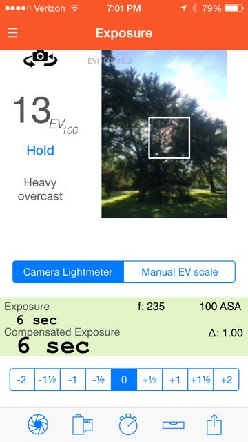
I designed and built another camera, and another, each an evolution from the previous. I improved the shutter, lightened the construction, and my photos improved. Learning to use a light meter and pre-calculating exposures with reciprocity failure went a long way towards better photographs, but I also came to know and trust my camera and films.

My Background

Three years ago, I had no idea what I was going to do with a 3D printer. Certain patents had expired and the technology was finding its way to hobbyists. I bought a kit of hardware and smoky laser-cut plywood parts and assembled them, intimately teasing out their secrets in the process. Meanwhile, I taught myself how to design objects for 3D printing, using tools like TinkerCad and OpenSCAD. Watching my new machine print an object, layer after layer, fascinated me. As my technical proficiency increased, my designs became more complex and I began to think about making functional objects instead of gnomes.

Which lead me back to pinhole cameras (and got me making pinhole photographs again). I was inspired by the Dirkon, a paper-craft pinhole camera design published in a Czechoslovakian magazine in 1979. A single printed template for the Dirkon could be used by many people to make a camera, and hundreds – possibly thousands – were cut out, folded up, and glued together.

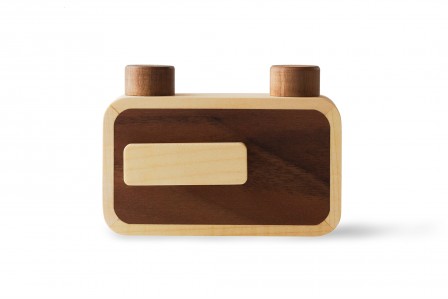
[singlepic id=194 w=200 float=left] [/singlepic]My first 3D printed pinhole camera design was an ugly 35mm job PINHE4D that worked beautifully. I then designed a large format 4X5 camera, the PINH5AD, which worked well too. The PINH5AD received some attention on various blogs and websites. I’ve since designed many more cameras and accessories, all of which are freely available for download.


[singlepic id=193 w=200 float=right] [/singlepic]Thingiverse.com is a free online repository for sharing 3D printing files, owned by Makerbot Industries, a 3D printer manufacturer. Posting my work on Thingiverse.com proved a perfect way to share my work and hundreds of people around the world have downloaded my pinhole camera designs. I continue to iterate my designs, improving and refining construction, details, and accessories and I receive priceless feedback from people who 3D print and/or use them. The cameras are licensed as “Collective Commons Attribution-NonCommercial” which means that anyone can share, download or 3D print them, or modify them to their purposes, so long as the original design is credited, and no money changes hands.

When I shared my first camera designs, some people were skeptical that they worked without any photographic proof. I now post every photograph I make with my pinhole cameras. I aspire first to make good exposures and then good art, and I don’t alter, manipulate, or otherwise edit my scanned negatives and slides. My photos are an objective history of my learning process – 3D printing and pinhole photography.

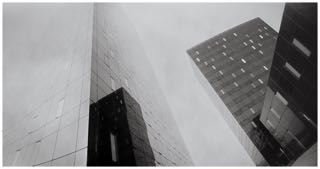
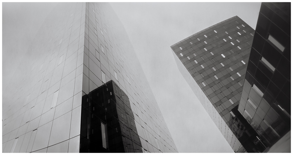
[singlepic id=188 w=500]Bridge, Taken with PIN5HAD[/singlepic]

About 3D Printing

If you’re not familiar with 3D printing, the concept can be mind-blowing. Essentially a tiny computer-controlled glue gun, the printer actually draws an object in three dimensions, layer by layer. For hobbyist / consumer-type FDM (Fused Depositional Modeling) printers, the “ink” is a thermoplastic polymer filament with desirable thermal, strength, and stability properties. The filament comes in rolls and is either 3mm or 1.75mm in diameter. Filament is usually about US$40/kg, but you can pay more or less.

An object is designed in a simple CAD environment, and saved as a file which can then be “sliced” for your printer’s capabilities and your preferences. Like a player piano, the 3D printer reads the resultant Gcode, obeying the the sequential instructions for building the object.

It is mind-blowing.

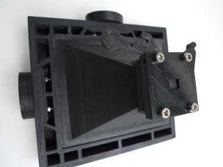
Designing for 3D printing is an interesting exercise. Each layer of a 3D printed object requires something under it for support. If you wanted to 3D print a miniature kitchen table, the best way to print it would be to flip it upside-down. Printing it right-side-up works fine until you finish printing the legs and then the next layer, the underside of the tabletop, is mostly printed over thin air. A 3D printer will happily try to make this happen, but expect a pile of extruded plastic spaghetti. The software programs that convert a CAD file to 3D printer instructions can usually build temporary support structures to support overhanging parts, but the table is an extreme example and the required support is wasteful in time and materials. To avoid “overhang” issues, I have designed my cameras as collections of discreet parts which must be assembled with a few bits of hardware. This lets me optimize each part’s design and orientation for “printability”, but they still require finishing and assembly.

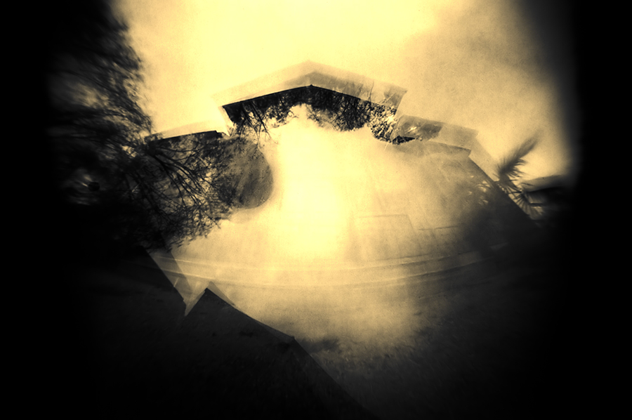
[singlepic id=196 w=500]Tank, Photographed with the PINHE4D[/singlepic]


3D Printing Options

[singlepic id=192 w=200 float=left] [/singlepic]I give my designs away because I want people to use my cameras
I recognize that most people do not have (or believe they don’t have) access to a 3D printer. This situation (currently) makes for a technological or economic barrier to entry. However, 3D printers are becoming more common, are becoming cheaper, and the sharing economy is making the technology more widely available. So, lacking a printer, how can you get one of my pinhole cameras?

Use a 3D printing service
Shapeways and Ponoko are two such web-based services, and I am sure there are others. My first foray into 3D printing was having custom Prius hubcaps printed by Shapeways, while I waited for my 3D printer kit to arrive.

These companies use commercial 3D printers that differ from the FDM consumer machines for which my cameras were intended. This would be an expensive experiment, but you could have a camera printed in a variety of materials. Of course, opacity and strength are considerations; so too are post-printing fit and finishing. Ceramic or aluminum are probably not viable options.

Peers with 3D Printers
There are a number of websites that serve to connect people possessing 3D printers with those who would 3D print something. I have participated in such a website as a 3D printer guy, but was discouraged by many designs that were unprintable. Coming up with your own design, from scratch, can take a lot of trial and error that is difficult without a printer at hand. Because of this, I’ve made sure my cameras are vetted designs that print well on a variety of machines, and you can be confident that taking my design to one of these printers should work well.

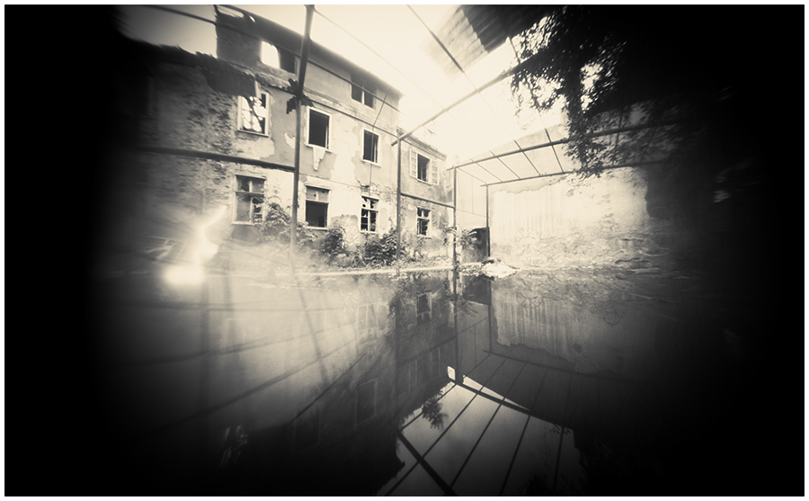
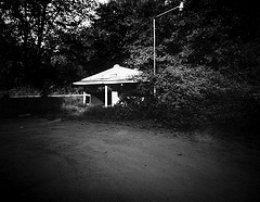
[singlepic id=189 w=500]Church, Taken with P66W[/singlepic]


Join a Makerspace or Hackerspace
Known by a variety of names, these are community-operated physical places, where people share their interests in tinkering with technology, meet and work on their projects, and learn from each other. Hackerspaces typically have 3D printers, laser cutters, assorted milling or wood-working tools, but every facility is different. Classes are often available. I learned how to program the open source CAD application OpenSCAD through a class I took at a local hackerspace. Expect to find very savvy people who can help you with your 3D printing project. Costs are often very reasonable but membership or hourly rates may apply.

Find a friend with a 3D printer
Ask around. When someone starts using a 3D printer, odds are good they will share what they’re doing with co-workers, friends, and family. This person may be able to help you. Expect to pay for time and materials.

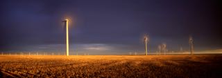
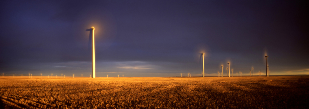
[singlepic id=191 w=500]Mt Si, Taken with PINH5AD[/singlepic]


Get a 3D printer
It’s not as crazy as it sounds! A versatile printer that can produce my cameras and other nifty things can be had for less than US$500. Obviously, I believe in the future of this technology and I hope my pinhole camera projects serve to evangelize and promote it. There are all manner of clever people designing clever things and sharing them online. You can join their ranks.

Some advice, should you set out on this adventure: Buy and use open source products whenever possible. There are a number of contentious patent wars being waged by big players against smaller players. This situation is ugly and threatens to stifle innovation and increase costs. MAKE: magazine regularly reviews 3D printers and is a “Maker” Consumer Reports. Secondly, a 3D printer can be a fiddly beast and you will benefit from assembling a kit for your first printer. You’ll save some money, and you’ll learn exactly how your printer works, making your printer a tool, rather than an appliance.

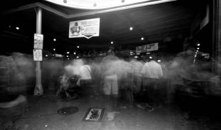
[singlepic id=195 w=500]Space Needle, Taken with P66W[/singlepic]


Buy a pinhole camera from me
3D printing is not a process that lends itself to mass-production. 3D printing is best applied as distributed production, meaning that everyone who wants an object can just make their own. Originally intended for rapid prototyping, it has become an engine for novelty and customization, but cannot compete with other production technologies like injection-molding or even sand-casting. I don’t want to be in the 3D printing business. I want you to 3D print your own cameras, assemble them and make awesome photographs.

However, I recognize that the intersection of pinhole photographers and 3D printer owners is a tiny set of interesting people. So, occasionally, I sell cameras to photographers on Tindie.com. I haven’t listed everything that I can make, and demand is small, but if you want a camera, I can print and assemble it.
CAD software allows me to accurately dimension focal lengths and frame sizes, and the pinholes in my cameras are hand-made with equal precision. I use 0.001-inch-thick brass sheet and “drill” the aperture with a tiny precisely-measured awl. Finally, the pinhole is measured under a digital microscope and examined to check for flaws and roundness. This degree of precision allows me to specify an f-number for my cameras with confidence.

[singlepic id=197 w=500]Tube, Taken with P66[/singlepic]


Guidelines for 3D printing one of my cameras

Source files
As mentioned, all my camera designs (et al.) are freely available for download from Thingiverse.com

Some of my designs feature optional or redundant parts that can be confusing. Parts are “plated” (grouped for printing multiple parts simultaneously) and available as discreet objects. Additionally, my recent designs have a zip file containing all the necessary parts to 3D print a camera. Start with one of those. If you have questions, or problems with the files, I am very accessible through the Thingiverse messaging system and/or comments section for an individual design.

Materials
For FDM 3D printing, the two primary filament choices are ABS (think LEGO) or PLA (think compostable picnic ware). Prices are usually comparable, but the materials differ in various properties.
ABS is absolutely opaque, resilient, but stinky when printed. It also has a vexing tendency to warp while being printed. PLA is more pleasant to use, smelling like maple syrup (really!), is not prone to warping, but is often translucent to light which is a negative for camera production. I have found a PLA made by Shaxon that is both opaque and cheap (US$25/kg) and there may be other suitable filaments from other vendors. There are a number of other plastics that people are experimenting with, but they tend to be pricey, fussy, and are typically transparent-ish.

Slicing
This may mean nothing to you at this point, but when you get a 3D printer, this will begin to make sense. The objects to be printed are files in an STL format. Essentially a numerical representation of a three-dimensional volume, this shape must be “sliced” into layers before printing. The slicer (ex. Slic3r or Cura) serves as a printer driver to your 3D printer and controls tool-pathing, layer height, speed, and infill density among others. The slicer generates a set of instructions in “Gcode” to explicitly tell the printer how to build your object. The Gcode controls the temperature of the extruder and the heated print bed, the speed of the extruder while printing, the diameter of your filament (Yup, it varies), cooling fans, among many other parameters. It is beyond the scope of this forum to walk you through all the possible settings for your slicing software, but most 3D printers come with a configuration to get your started.

Once you have set up your slicer software, the important parameters are:
Layer Height – All my camera’s parts are some multiple of 0.20mm in height. Setting layer height to 0.20mm will provide dimensional accuracy.

Infill – I usually print with at least 50% infill for durability, but you can get away with less if your filament is opaque or you want to save some time printing. Infill can take a number of forms (rectilinear, hexagonal, and exotic mathematical structures), but simple is often best.

Top and Bottom Layers – Again, opacity and strength are very important, and I use at least three solid layers top and bottom. This means that the 3D printer will print three solid layers before it begins to use a fractional infill for the interior of the part. Similarly, the printer will print the top three layers of any surface as solid. The first solid layer may be rough or droopy, but subsequent layers will smooth out.

I hope you are intrigued by 3D printing and I sincerely hope you print one of my cameras!


Paper Negatives: Refining the Process

If you’ve been following ƒ/D closely, you’ve probably seen that we’ve featured some of Marko Umicevic’s images before (here and here). His images of Croatian scenery carry a distinctive smoothness in tonality and transitions that suit the subject matter expertly.

Marko often relies on paper negatives. It’s a medium I’ve personally used a little, and have always been intrigued to learn more about. I was surprised to see a particular aspect of Marko’s process notes: R09 1+100. I thought it was a typo, and then when I saw his Under the Trees, I saw that it was R09 1+200, and I had to pursue this further. R09, the modern incantation of Rodinal, is more often than not a film developer. Moreover, when used for paper, the recommended dilution is usually 1+10 or 1+20.

Over the course of a few emails, I got the chance to quiz Marko about his Rodinal paper development technique further. I’m pleased to present the highlights of that conversation here.

Marko, when I look at your images, and consider that you’re using Rodinal in 1+100 or 1+200, it appears that you get a longer tonal scale than you’d normally get from a paper developer. Is that accurate?
You are right. That’s what Rodinal does in comparison to standard paper developers when used at higher dilution than normal! At 1:200 it works very slowly, doesn’t penetrate deeply inside the paper base and reduces silver mostly on top. This “flat-top” procedure (similar to water bath) evens out the contrast more efficiently since it contracts highlights that are prone to blow out when development starts! (And highlights are something to keep in mind when dealing with paper negatives) Rodinal works as an excellent paper negative developer and allows you to fine tune contrast of your images. Unfortunately, at higher dilution it’s quickly exhausted and that requires extra precaution at development sessions.

Wide tonality of some of my images, beside highly diluted Rodinal, is partially result of fiber based grade 2  paper I’m using (conventionally: normal grade paper). Lower grade gives lower contrast, i.e. better or wider mid-tone values while fiber base due to its higher amount of deposited silver brings to overall picture depth. Same effect can’t be achieved with VC/RC paper!

So, it’s a balance between Rodinal dilution, developing procedure and graded FB paper I’m used to and know very well. Not to mention the importance of exposure that needs to be as exact as possible.

Chrysopoeia, ©Marko Umicevic 2015

Are you using any agitation in your process? Or is it stand development?
It’s usually a stand development with very little agitation or if any. In the case of Under the Trees – due to high scenery contrast – negative was developed with almost no agitation at all. The thing is, while proceeding with stand development, if I see that developer is exhausted or near exhaustion and works extremely slowly I would agitate it if necessary. This would bring some power to it but results wouldn’t be the same as with stand development done with freshly mixed batch.

Outer Walls, ©Marko Umicevic 2015

Are you pre-flashing your paper negatives first?
When working with pinhole camera and paper (and I do both almost exclusively) I try to keep the whole process as pure as possible. Pre-flashing paper can slightly increase the emulsion speed and consequently help one keep the contrast inside normal/usable scale if exposure is based on shadow values and measured under difficult or harsh lightning. However, for me if the light isn’t just right – soft, subdued and kind of “touchy” with mostly open shades – I’ll try not to do the picture. That makes pre-flashing in my case irrelevant. Also, I try avoiding the use of any sort of filters, be it color or UV.

Hunted, ©Marko Umicevic 2015

What ISO do you generally find works best for this configuration?
I usually rate my paper (FB Fomabrom grade 2) at ISO12

Speaking of exhaustion, roughly how many negatives do you find you can develop in a batch of Rodinal 1:100 or 1:200?
In my experience, 1L of developer solution at 1+100 is roughly enough for 3 sheets of 8x10in paper, while at 1+200 one can count for 2 sheets. Keep in mind that we are speaking of double weight FB paper! Considering exhaustion, highly diluted Rodinal in a tray has full working life of roughly 25 minutes at 20°C. So, when developing at higher dilution I try to bring picture to life very slowly, but starve to finish the procedure fast. With practice and confidence this quickly becomes a routine and a method.

Leaning Towers, ©Marko Umicevic 2015

For those that aren’t familiar with the Development by Inspection technique (as opposed to time and temperature), can you describe the process? How do you know when to pull the print from the developer?
Basically, developing paper negatives is very similar to developing enlarged prints in a standard darkroom processing. But, unlike standard paper developer and standard procedure that mostly urges for fixed time, developing paper negatives in Rodinal is less restrictive and more open to process variation at the development stage. Higher Rodinal dilution brings even contrast at prolonged development time allowing one to pleasently observe, control and eventually modulate picture tonality under the safelight. Decision like „should I agitate or not“ or „can I stop it now“ are all made under inspection! Also, when working with Rodinal one has to keep in mind Rodinal’s „single-shot nature“ genuinly formulated for film and not for paper! Issues of this old chemical formula comes to life at stand development in a tray that in my configuration often lasts between 8 to 20 minutes. Paper fogging from safelight or developer oxidation are expected difficulties that I need to count on. You would rarely experience this with standard paper development in standard darkroom procedure – be it print or negative.

In Rodinal my paper negatives are usually developed as follow:

Firstly, I push the paper with the emulsion side facing down inside shallow tray filled with developer and with the help of tongs try to keep the paper beneath developer surface until I feel its thoroughly soaked. Then I slowly (!) agitate the tray for a brief moment.

After first minute I flip the paper upside so I can see how the picture is coming out. At 1:100 properly exposed highlights starts to occur after about two minutes. Keeping an eye on highlights when developing really starts and observing the speed they are coming out makes help in evaluating final contrast and gives signals for further agitation if necessary. Developing is finished when shadow details are fully developed. That’s the point when I pull the paper out of developer tray.
Dilution and Rodinal developing time in a reference to desired negative contrast are evaluated on my expectations and sometimes by the notes I write on the exposures and scene/subject light values. Experience in working with paper and darkroom materials I’m familiar with plays great key of roll in my processes. Usually when I standardize the procedure (exposure/paper/developer combination) I can count on timing what makes developing by inspection at least for the sake of contrast control – not so necessary. Still, I enjoy it very much to watch how picture is slowly drawing itself and this work of magic can be quite thrilling on larger sheets of paper!

Mirror Meditations, ©Marko Umicevic 2015


More of Marko’s work can be found on his Flickr page.


Changing Light: Managing the Long Exposures

Many of us who’ve been around photography for much time at all have been introduced to the concept of the Golden Hour – that time just after sunrise and just before sunset. The light during this time can be truly amazing, and has served as the drama of numerous photos over the years.

The challenge for us pinholers though, is that our cameras often require a longer exposure during these times of day. Moreover, as the exposure time increases, the intensity of the sunlight can change rapidly, leading to complexities in our exposure. The effect can be compounding, especially on slower capture methods such as paper negatives.

In my photo, Elliott Bay at Dusk, I had my Zero Image 4×5 loaded with a paper negative and pointed at a scene that originally metered at a 5 minute exposure. By the time I was done shooting, the scene was metering at 20 minutes. Overall I exposed for 15 minutes and got a result I’m quite happy with, albeit with quite a bit of nailbiting for that 15 minutes.

Elliott Bay at Dusk, ©Kier Selinsky 2015


For this article we want to learn a bit about working with the light during these challenging times of the day, and I decided to interview Eddie Erdmann for his insights. A quick look at Eddie’s Flickr profile shows that he’s quite adept at shooting pinholes during sunrise and sunset, and can speak with a bit of “been there, done that” authority on the matter.

Do you have a specific amount of time before sunset or after sunrise that you find works best? 
It varies. Sometimes the best part of a sunset occurs before the sun is down, and sometimes it occurs well after the sun has dropped below the horizon. If I have a particular location in mind for shooting the sunset, I will try to arrive 30 minutes to an hour before the sun goes down so I can watch and wait for the scene to unfold. In Alaska sunsets can last for a very long time in the summer, so when shooting a sunset here at that time of year, I may end up hanging out for a couple hours. When I’m in the Lower 48, particularly on the Gulf Coast, sunsets are fairly quick because the sun goes down at a much sharper angle. Sometimes I don’t even bother to take my cameras out of my bag because the sunset isn’t especially inspiring. When I’m shooting sunrises, I employ the same 30-minutes-to-an-hour approach. I find that the best moments occur from 30 minutes prior to 30 minutes after the sun rises.

Eddie Erdmann - Judith Gap Wind Energy Center at Sunset
Judith Gap Wind Energy Center at Sunset, ©Eddie Erdmann 2015

How do you meter for a sunrise or sunset? 
I usually spot-meter an area of the scene that I estimate should fall within the middle range of brightness values and go with that exposure time. Usually I choose a cloud that isn’t catching the full rays of the sun. If I’m shooting with Fuji Velvia, I tend to spot-meter some of the brightest parts of the scene as well so as not to blow out the highlights too much. When shooting with Kodak Ektar or black-and-white film, I don’t worry so much about that.

Do you adjust your exposure time as the light changes? 
I usually decide on an exposure time before I open the shutter. I determine this time by metering, compensating for reciprocity if necessary and then tacking on a few extra seconds (or as much as a minute or more for longer exposures) to accommodate the diminishing light of the sunset (or subtracting a few seconds for a sunrise). I find that rough approximations do just fine when working with long exposure times.

Eddie Erdmann - Pinhole Sunrise on Dauphin Island
Pinhole Sunrise on Dauphin Island, ©Eddie Erdmann 2015

Do you find that you need to adjust for reciprocity in the middle of an exposure?
If I determine that the scene will require an exposure time that will require me to take into consideration the film’s reciprocity characteristics, then I will do so, but I really don’t think about this once I’ve opened the shutter. I meter the scene, and if necessary I consult my film’s reciprocity data to decide how much I need to adjust the exposure. Then I open the shutter for the amount of time that I’ve determined would be best. A good thing about pinhole photography is that because the exposure times tend to be pretty long, you really don’t have to worry about being terribly exact. I don’t spend a lot of time calculating exposure times. Usually, it takes me only a few seconds to meter the scene, consult a reciprocity-failure chart (actually, at this point, I rarely look at charts–I use only a few different types of film, and I have a decent understanding of their reciprocity) and perform a simple calculation in my head.

Eddie Erdmann - Mobile Bay Just After Sunset
Mobile Bay Just After Sunset, ©Eddie Erdmann 2015


We thank Eddie for taking some time out of his hectic schedule to help us capture the amazing light that exists at these times of the day. Hopefully some of this experienced input helps our readers to take advantage of the changing sunlight! Do you have additional questions? If so, put them in the comments and we’ll follow up with Eddie to respond back to you!


On Pinhole Camera Geometry: a Brief Overview

Editor’s Note: For this article, ƒ/D is pleased to present a contribution from guest author Delio Ansovini. We’ve featured Delio’s work previously on ƒ/D, where he showed an expert hand at still life subjects. If you look at his work enough, one thing that quickly begins to stand out is his exacting attention to detail in the framing of his shots. As a trained engineer, he has a firm grasp on the geometry involved in a camera’s configuration, and he’s graciously offered to put together some thoughts on how he approaches the subject for us. So without further ado, we present Delio Ansovini’s take on Pinhole Camera Geometry.


Geometry matters – because it is the geometry of a pinhole camera that defines the image taken with it.

The pinhole diameter, the size of the negative, the distance and position of the film and pinhole from each other, and the orientation of the camera toward the subject all affect the resulting image for one simple reason: light travels in a straight line.

Perspective geometry, which is stated simply as ‘…a way to give an illusion of three-dimensional depth when drawing on a flat surface’, very reliably does the rest.

Once we understand these concepts and techniques, the lack of a viewfinder doesn’t need to stop us from pre-visualizing the results.

First: What are view lines?

View lines provide us with a visual axis that defines what will be captured by the pinhole in the final image. The lines are a simple tool that you can apply to any camera to help with your visualization.

[singlepic id=78 w=350 float=left][/singlepic]Top Red View Lines
By visually following the line from the camera, you can observe what is included in the shot. Anything inside the extended two lines will be in; anything outside them will be out of the shot. It helps to use a pointer – I use a pencil positioned on the view line and I look at the sharp end pointed toward the subject. Others use 3 screws and line up the 2 screws with the subject. Regardless of your method, the top red lines are to help you visualize what will be included from left to right in your shot.

Side Red View Lines
Just as explained with the top lines, the red lines on the side of the camera extend from the edges of the film plane to the axis with the pinhole. For a 4×5 negative, the corners of the frame holder opening are the points to project to the sides of the box. For 6×6 the corners of the film mask are the ones to use. Again, like the top red view lines, you can visually follow the lines from the camera to the subject to visualize what will be in the shot, but for these lines, you’re visualizing what will be included from the bottom to the top of the shot.

Blue Horizontal and Vertical Lines
The blue projection lines from the pinhole to the edges of the camera are important to consider when applying your view lines. If the pinhole is recessed from the front plane of the camera, recess the convergence point of the view lines by the same amount.

[singlepic id=80 w=150 float=right][/singlepic]The Four Converging Planes
If you extend out the Red View Lines diagrammed above, you have an ever broadening plane extending from the front of the camera. The result is that the four intersecting lines generate four converging planes that extend from the film plane and intersect at the pinhole, then extend into the space beyond the camera.

To the right is my 4×5, f175 with the 130 deg view lines made with 2mm wide automotive vinyl pin striping. Note how if we visualize the extension of the View Lines towards the subject, we can see what the camera sees at that distance.

Second: Something borrowed from lens photography: the diagonal angle of view

You can find this angle value the fun way (do-it-yourself for those who like trigonometry) or “cheat” and use the app given below. Two factors directly change what the pinhole camera registers on a flat negative. First is the distance from the pinhole to the negative, and second is the size of the negative.

First, let’s look at the size of negative. Imagine that the image projected from the pinhole is a cone with a circular base sitting on top of a 6×6 negative while you are looking at the pointed apex. For a square negative, the vertical and horizontal perspective would not change since[singlepic id=77 w=350 float=left][/singlepic]the cone base will be tangential to both the vertical and horizontal sides, or for that matter with a larger diameter to each opposite corner of the negative.

The geometry will be totally different if the negative is, say 6×12, and we keep the height of the cone (the camera focal length) constant. If we look at the angle formed by the diagonal of the negative (from corner to corner), it is much larger than the 6×6 negative, even though the cone angle remains constant for both the vertical and horizontal planes as before. We call this diagonal measurement from corner to corner of the negative the diagonal angle of view. The diagram helps to visualize the concept.

This means that if we want to obtain a certain geometric perspective in our pinhole image and, for whatever reason, we have to change the negative size, we can use the diagonal angle of view as the constant factor while changing the distance from the pinhole to the negative. In short: a 6×6 cm. pinhole camera with focal length of 28mm has a diagonal angle of view of 113 deg.; the same as an 8x10in. (20.3×25.0cm.) pinhole camera with focal length of 106mm.

The two cameras will give you the same geometric perspective and both would be considered rather popular wide-wide angle pinhole cameras. Instead of the above, you can find the diagonal angle value with this handy program or this handy website.  Both the program and the website have features that calculate the diagonal of view based on your camera measurements. 

There are also personal reasons why I consider the diagonal angle of view important in designing or choosing a camera for a specific shot: I enjoy being able to have some control over the image. Moreover, I hate cropping 2/3 of the negative needlessly – film is too expensive to waste.

The following photos illustrate the visual difference in geometric perspective according to the diagonal angle of view and camera position on a 6×6 negative.

[singlepic id=81][/singlepic]
[singlepic id=83][/singlepic]
[singlepic id=84][/singlepic]
[singlepic id=85][/singlepic]

Note: the almost normal perspective lines in the first, the predominance of the hand railing on the second, and of course the lines divergence and convergences on the last two.  

Third: light gets tired travelling longer paths

The truth of the matter is that the path from the pinhole to the corners of the negative is longer than the one to its center. And it gets darker and mostly “unpleasant” for diagonal view angles above 130 deg.

On the other hand we photographers do love the drama of the vignette, the exaggerated convergence of lines, and the elliptical distortions in the corners. But there are limits, so we crop what we can’t distinguish or appreciate anymore.

I settled on 130 deg in my designs, based on what I like and my processes. Other will choose according to their own objectives and skills.

Some time ago I made a 4×5; f140; 21mm focal length; 149 deg diagonal view angle camera;  following are the camera and the drastically cropped image taken with it.

[singlepic id=72 w=325 float=left][/singlepic] [singlepic id=87 w=335 float=left][/singlepic]

At this point it is not only about geometry anymore: film used, exposure methods, developing products and methods all will contribute to getting details on the corners of your image and make the vignette less severe.

But above all it will be what you like and what you see in the images that you have made that counts. This is what makes pinhole photography so amazing.

Carrying Your Kit: The Getaround

One of the most difficult aspects of practicing photography, for many photographers at some point or another, is carrying all that damn gear. “Traditional” (e.g. lensed) photographers probably have it the worst, as anyone who’s lugged a few constant aperture zoom lenses or a full large format rig can attest. While we pinholers get a break by not having to carry glass, we still have our challenges getting our kit to the photo destination.

The best camera is the one you have with you,” as the saying goes. Indeed, nothing sucks like walking by the perfect shot without your trusty pinhole at the ready. Therefore, a key to this beloved hobby of ours is keeping a camera with you as often as possible. For many of us, that means commuting to/from work, joining friends on the evenings or weekends, shopping, parks, etc.

So for today’s article, I want to share my Getaround setup in the hopes of spreading ideas to help you shoot more. As always, if you see something that could be improved? Share it in the comments and help all of us out as well.

First – here’s a picture of my Getaround:
Pack

And here it is, “exploded”:
Pack exp view


Let’s go through it piece by piece.

Cameras

I always carry at least 2 cameras, sometimes 3 or 4. Why? First off, so that I can have a color and a black and white option. At a minimum, I want that. Pictured here are my Pinholga (converted by yours truly) and my Zero Image 6×9. I tape the current film label to the back of my cameras so that I can remember which is loaded with what. Not pictured here, but often in my pack, is my Zero Image 4×5. These 3 cameras give me 5 configurations: 6×6, 6×9, and 4×5 (25mm, 50mm, & 75mm focal lengths). On particularly ambitious days, I’ll add in my Polaroid. That’s a lot of options!

Packing

Notice that I don’t use a traditional camera backpack, and that’s entirely on purpose. I have two reasons for this. First, I wanted something that didn’t scream “cameras!” but was fully featured including a laptop sleeve. Second, the backpacker and urban market has a lot more options that have better suspensions than normal camera bags. Osprey is my brand of choice and for good reason – they are well renowned for their suspension. When I lived in Seattle, I could carry this bag, loaded with 25 pounds of camera and laptop gear, for hours and still be fine. That’s a damn good suspension system.

Inside my normal backpack I have a camera bag insert. This is basically a camera bag padding system that you can stuff into any backpack. They come in a handful of shapes and sizes and will keep your gear protected in your backpack. This was key to my feeling comfy with a non-padded backpack.

The backpack and camera bag insert are very key to my Getaround. By having something that I can take everywhere, I can easily have plenty of cameras with me at all times.

Tripods

Yes, I always carry two tripods with me. What you see here are my Slik mini tripod with ballhead and the infamous Gorillapod. Why these two? First, their weight is so minuscule, there’s hardly a penalty for carrying a second one. Second, while the Gorillapod is invaluable when you need to mount on something elevated like a fence rail, it’s a complete pain in the ass when you just want to be on a flat surface and level the camera. In addition, the Gorillapod isn’t quite as stable as a normal tripod, so it’s definitely reserved for those shots that cannot be done any other way.

Not shown here is my full size tripod, which I carry when I anticipate having the need for that much flexibility. See the loop on the bottom center of the backpack? That loop, plus a tie down, allow me to mount the tripod in the centerline of the backpack. This allows for a much easier carry to your shooting location, so when you get there you still have the wherewithal to compose your shot.

Various Sundry

A regular daypack is also superior for just carrying…stuff. We all have the normal needs for a photo trek, so having flexible room for it is a big payoff. Some additional photo related things I carry with me are a pocket level for my 4×5, extra film of course, and my trusty locking cable release.

What do you carry?

I wanna hear it in the comments!


Building Pinhole Cameras: The Meta-How-To

One of the coolest things about pinhole photography – and honestly a key component that got me hooked – is the fact that you can build pinhole cameras yourself and out of anything that you can make light-tight!

Your imagination and craftsmanship are the only limits in this game!

There are already tons of links out there about how to build a pinhole camera. You can spend DAYS reading about how to build a pinhole camera. Believe me – I have. If you have a knack for DIY, figuring out how to blend multiple plans into a single Frankencamera is a lot of fun too!

It is not my intention to add to the piles of how-to articles. We’re going to add something different – this is going to be a Meta-How-To (yeah I just made that term up).

In this article I’m going to arm you with the info you need so that you can decide what type of camera to build.

Modifications, Freshly Built or Modifying an Existing Camera

Some plans require you build a camera body; while others have you repurpose an existing container. Depending on your tools, abilities, or available time one approach may be more appealing than the other. Let’s look at some options and considerations for each choice.

Building a container yourself

  • At a minimum, you must be able to make the camera body light tight.
  • If you’re going to use paper negatives, the film holder can be fairly simplistic.
  • If you’re going to use roll film, consideration needs to be made for the winding mechanism (more on that below).

Using a prebuilt container

  • Feel free to repurpose anything, an old tea tin, a ceramic tchotchke, an old shoe box…
  • You’ll need to paint the interior to make it flat black (no reflections!)
  • You can make a camera out of any oddball thing you find, making you the hippest kid on the block.
  • The same considerations will still need to be made in regards to film holder mechanisms.

Modifying An Existing Camera

  • My favorite option because part of my joy is to pull apart the camera to see how it worked.
  • One advantage is that your film handling structure is already installed –  for film this is a huge advantage
  • Old cameras can be found in the attic or the antique store – often for under $10!

Paper vs Film vs Instant

On it’s surface, your choice of film or, more technically, sensitized material, seems simple.  And it is simple!  It is important, though, to choose a medium that you’ll enjoy. Choosing the right materials will increase your likelihood of enjoying this pinhole journey you’re embarking on.

Paper Negatives

  • Can be used in many different cameras
  • Needs to be processed at home
  • Requires the tools, chemistry, and skills needed to develop photo paper
  • Black and white only

How to use:  

Paper negatives involve using black and white photographic paper in your camera as a negative. The paper is cut down to size and placed inside the camera body and used like you would film.  Remember to keep the paper under safelight while you are doing the cutting and placing into your camera.  We don’t want to ruin the paper before we expose it! After you expose the negative and develop it, you can either contact print it with another piece of photo paper or use a scanner to digitize and invert the photo on your computer. Paper negatives are the slowest film type, usually about 6 ISO, however they provide a great and unique image quality that you’ll get from nothing else!

Film

  • Camera design needs to have considerations for film handling.
  • Multitude of films to choose from:  Eg. 35mm, 120 (medium format), or large format (such as 4”x5”)
  • Can easily be sent to a lab for processing and scanning, or black and white can be processed at home
  • Black and white or color

How to use:

When building a film fed pinhole camera, the important thing to consider is the winding mechanism. We’ll set aside the use of large format film for now because that’s very specialized. If you don’t have good structural support for the 35mm canister or 120 spool, you can run into binding issues making it difficult or impossible to wind the film. The film must have a sturdy holding mechanism and also a smooth method of winding the film without disturbing the light tightness of the camera body.  If this makes you nervous, modifying an existing film camera might be more your speed until you have gotten more comfortable with your creations. 35mm and 120 are both roll format films – 35mm being the common canister you’ve often seen; and 120 being a larger film on a spool with paper backing. Both 35mm and 120 are fairly economical, with 35mm being the cheaper option. Both films can be sent to a number of labs around the country for processing and scanning before returning to you.

Instant Film (e.g. Polaroid):

  • It’s easiest for processing so long as your camera must have proper roller system for it
  • Want your photos now? This is super easy – snap in a pack, take the pic, rip the film out, and wait 60 seconds!
  • Black and white or color

The right equipment is necessary. Don’t worry – finding it is not that hard. Hit the antique store and look for old Polaroid Land Cameras. When you find one, open the back and make sure the rollers are clean. Then Google the model number and see if it takes Polaroid 669 film. If it does, you’re in luck – Fuji’s got your film needs covered! All you have to do is remove the lens and put in a pinhole.

Other Considerations

Whatever your film choice, consideration must be given to how your camera will be used “in the field”. Are you ok with only changing the film or paper negative at home? Then little consideration is needed. However if you want to be able to change sheets of paper, rolls of film, or packs of instant film, some forethought is necessary for your design. All this means is – think about your camera design and what it will take to change the film. Is this a process you’re comfortable with doing in the field? Do you care?

Pinhole Sources

The traditional way to get yourself a pinhole is to literally take a tiny pin and slowly bore a pinhole into a piece of aluminum. Here’s a bunch of videos to help you with that. If you’re just toying around, this is a great way to get started.

When you get a little more serious, and want your pinholes to be more precise, you can get laser drilled pinholes to exact diameters.  You can sometimes get these mounted onto a larger disc for easier handling, while others will just be a tiny piece of aluminum. There are lots of options for you to choose the type that suite your own needs.Here’s a Google to get you started.

You might be wondering what size pinhole you should use. Well, lucky for you, there’s a calculator for that!  Just plug in your camera measurements and it’ll guide you towards the right size. Just note – laser cut pinholes are usually measured in microns, and 100 microns is a tenth of a mm (e.g. 100 microns = 0.1mm).

Random Features

There’s lots of room for creativity in your designs.

  • Try a  panoramic camera with a curved film plane to avoid distortion and vignetting over a long film plane.
  • Integrate a film mask to get a super crisp edge or custom image markings
  • Bullseye bubble levels for quick level reference
  • Cable release adaptors are by no means a must-have, but sure can be nice in certain situations.

Questions?

I hope that I’ve helped you leap a few steps down the path to figuring out which plan works best for you. But, this is just one article, so I’m sure there’s other questions. Feel free to put them in the comments below and I’ll get to them soon!


Circles of Confusion

At ƒ/D our mission is not only to inspire, but to inform in a way that we hope leads to further discovery. Today I want to dive into some of the details of how a pinhole camera “works” so that we can all better wield this tool we’ve chosen. This is a somewhat technical subject, but I’m going to do my best to stay above water. I’m going to do the math for you – but there’s a link at the end of this for those that revel in complicated math and details.

Circles of Confusion

In photography, “Circles of Confusion” (CoC) are what make up the image that you see in the final photo. Blurry portions of photos taken with a lensed camera are made by large CoC, and sharp portions of a photo are made by small CoC. So what are CoC? In a word: points. Fine detail is produced by the optics of the camera resolving the many rays of light that make up that detail into many tiny tiny points. Blur (not including motion blur) is produced by out of focus areas that are resolved into much larger spots. If you get your face super close to your screen, you’ll see everything is made of thousands of little dots, called pixels – this is very similar to a photo’s CoC.

A pinhole camera works by creating CoC’s that are all the size of the pinhole. Light travels in a straight line, and in a scene there’s gazillions of straight lines reflecting off of your subject. Those straight lines travel through the pinhole, at the size of the pinhole, and then hit your film. Contrast this with a camera that uses a lens – that lens works by bending the light and focusing it to a much smaller CoC, and thus a much greater amount of detail onto the film plane.

The Pinhole Look

First, let’s take a second to define what the “pinhole look” is. I believe it can be characterized by 2 things:

  • infinite softness and
  • infinite Depth of Field

There are those that would argue that qualities such as vignetting, distortion, and long exposure are also part of the pinhole look, but each of those qualities can either be designed out of a pinhole camera or mitigated with light and film speed.

Infinite Softness

Now that we know what a CoC is (again, Circle of confusion), let’s take a second to understand how that translates into the aesthetics of a pinhole photo. Your typical pinhole is going to range from 0.2mm to 0.5mm. Because of the physics involved, your CoC is going to be roughly the same size – not exactly the same size, but close enough for this article. So a pinhole camera that has a 0.2mm pinhole will have CoC that are about 0.2mm as well. By comparison, a typical DSLR with lens is producing CoC that are about 0.019mm. That’s 10 times smaller! That’s also 10 times sharper.

Since the CoC produced by a pinhole camera must be many times larger than those produced by a DSLR or just about any other well designed lensed camera, we get softness at all points of the photo as a result of the pinhole photograph.

“Infinite” Depth of Field and the Real Limitations

Now we know that the resolving sharpness (CoC) of a pinhole camera is much less than that of a DSLR. But what does that really mean? Well, the first impact is in Depth of Field. Recall that Depth of Field is the distance over which parts of your subject will appear to be in focus. It’s often said that pinhole cameras have an infinite Depth of Field, but that’s a little misleading.

It’s misleading to say that pinhole cameras have an infinite Depth of Field because while that is technically true, the practical Depth of Field is limited by the CoC. Why? Consider a landscape photo, with some trees that are 500 yards away. Let’s say you’re shooting this scene with 2 cameras: one a medium format pinhole camera with a 0.3mm pinhole and the other and the other a medium format lensed camera set on f/22 for maximum Depth of Field. Imagine those trees, when projected onto the film, are 1mm tall. In your pinhole camera, those trees are going to be represented by about 3 CoC (1/0.3 = 3.3). In your lensed medium format camera, which produces CoC of 0.053mm, there will be about 20 CoC. Remember, more circles equals more sharpness! So while the pinhole camera has infinite Depth of Field, it runs into a limitation of resolving power because of the CoC.

At this point, you might get the bright idea to just use a smaller pinhole. Hold your horses! If you go smaller than the prescribed pinhole for your camera, physics is going to put a stop to you right there. But the reason why is whole ‘nother article. Suffice to say, for now, go with the size pinhole that’s prescribed for the dimensions of your camera.

The Impact of Circles of Confusion

So what does all this mean? What the hell is the point? What are you getting in exchange for this headache? Armed with this information, we can make better choices for our artistic vision.

Digital Workflows

If you’re like many pinhole photographers today, you are shooting with film or paper negatives, and then scanning them into your computer where you apply some digital touching up before publishing. CoC make it all the more important in this workflow to really nail your exposures. Having less detail in the negative means there’s less detail to work with later. Dodges and burns that would have worked on a DSLR photo will look fake on a pinhole photo, because there’s less detail to manipulate. This means that you’ll want to ditch that habit of telling yourself you’ll photoshop it later, and instead take up the mantra: “Get it in camera!”. Perhaps a refresher in ole Ansel Adams’s classic, The Negative.

Film Formats

Your choice of film format can have a great impact on your level of sharpness. This is true in all photography, but especially true in pinhole. Consider our previous example – the medium format pinhole camera with the 0.3mm pinhole. All things being equal – the scene, the exposure, an appropriate pinhole size, and the angle of view of the camera – a 4×5 camera will produce 2.5x more detail than the medium format camera! Now of course we’re not in pinhole photography for the sharpness. But there are times when sharpness needs to be considered. If your subject, or the scene, includes lots of details and, further, you want to highlight some of those details, you may want to consider using a 4×5 or even 8×10 camera. At other times, when the scene or your vision is free of fine details, you can safely use your medium format or 35mm pinhole camera.

Composing a Shot

What do you envision from the final print from the photo you’re taking? If the magic in this shot is depending on some distant or small piece being recognizable, consider the amount of resolution your film will have based on your pinhole size. No way does this mean get out the ruler and old trigonometry textbooks – but rather take a moment to visualize how large that detail will be on the film plane and if you’re going to have the desired detail needed. Granted – much of this relies on practice, but we’re here to flatten the learning curve, not remove it!

Wrap Up

Hopefully this helps you be a better pinholer now and for many years to come. Again, in short:

  • The softness in the details of pinhole photography means you have less detail to work with during burning and dodging, so get the exposure right!
  • If you need more detail, use a larger format
  • Visualize the final print and make sure that you’re framing for the detail that you feel is needed to make the photo work!

As promised, if you need further info, including the detailed math behind CoC, there’s a very good write-up on Wikipedia.

Did I bring clarity or stir up the mud? Let me know in the comments below, or hit me on twitter @fslashd


Technique: Multi-Lapse

A recurring component of pinhole photography is the long exposure time. Even out in bright sunlit skies we’ll often find the proper exposure to be 1 or 2 seconds. The result of course is that parts of your composition which are in motion – flags, people, trees in the wind, etc – will blur from the motion.

Seeing what the motion will do on the final photograph is part of the appeal of pinhole photography. Sometimes the results surpass our expectations. Continue reading Technique: Multi-Lapse

A Survey of Cameras

By this point we may have inspired you to dream of making your own wonderful pinhole photos and explore how this technique might help all of your photographic endeavors. One of the first decisions to make is exactly how you might go about doing that. Never fear! While in olden times some of us had to scratch and scrape together a hodgepodge of a camera, nowadays there are very high quality cameras available for very reasonable prices. Continue reading A Survey of Cameras